Construcciones MJW
1 / 5
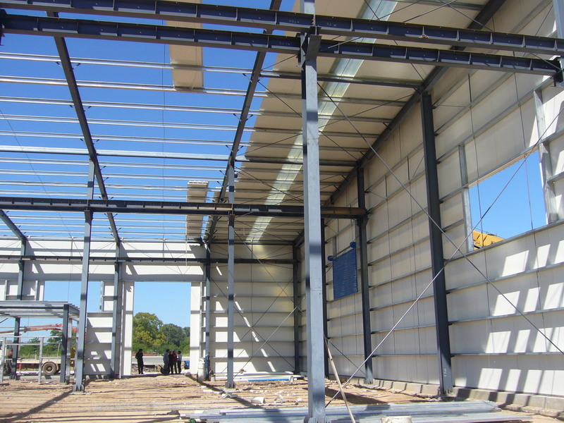
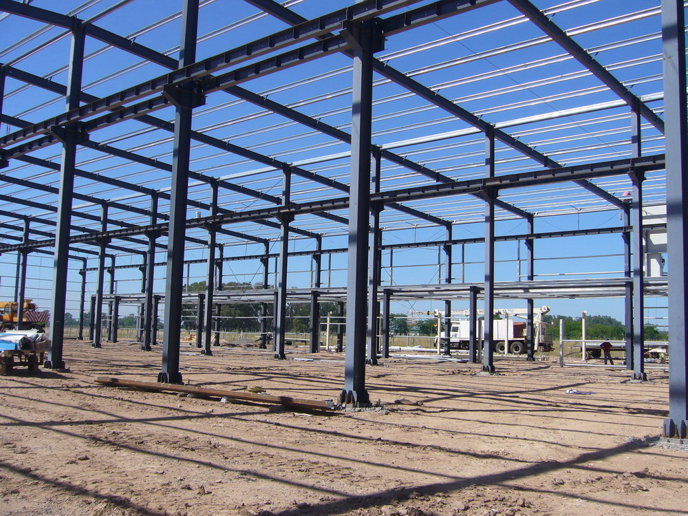
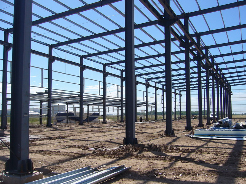
Pre-engineered steel buildings are steel structures built over a structural concept of primary members, secondary members, roof and wall sheeting connected to each other and various other building components.
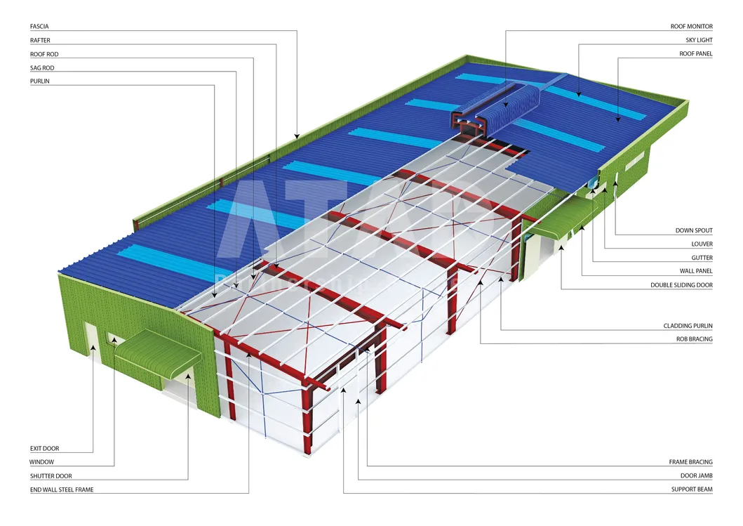
These buildings can be provided with different structural and non-structural additions such as skylights, wall lights, turbo vents, ridge ventilators, louvers, roof monitors, doors & windows, trusses, mezzanine floors, fascias, canopies, crane systems, insulation etc., based on the customer's requirements. All the steel buildings are custom designed to be lighter in weight and high in strength.
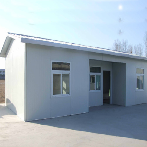
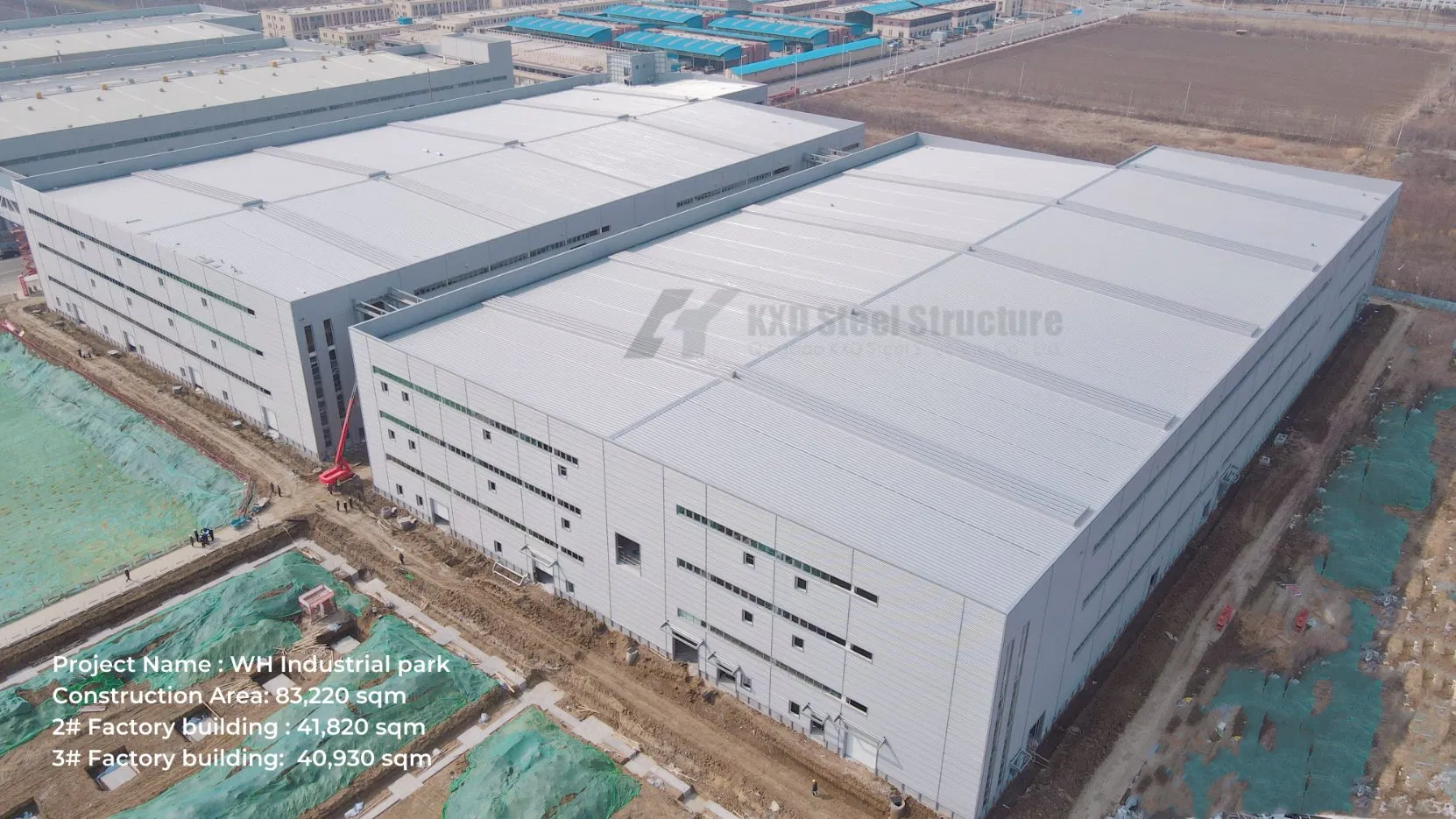
Pre-Engineered Buildings are the most flexible solutions for contractors and owners. With the advantages of low cost, high durability, perfect quality control and fast erection; PEBs are used for various applications such as factories, warehouses, logistics centers, showrooms, shopping malls, schools, hospitals, community buildings, etc.
The application of PEBs:
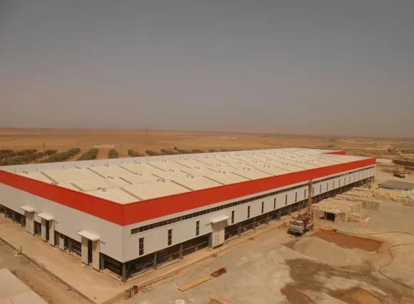
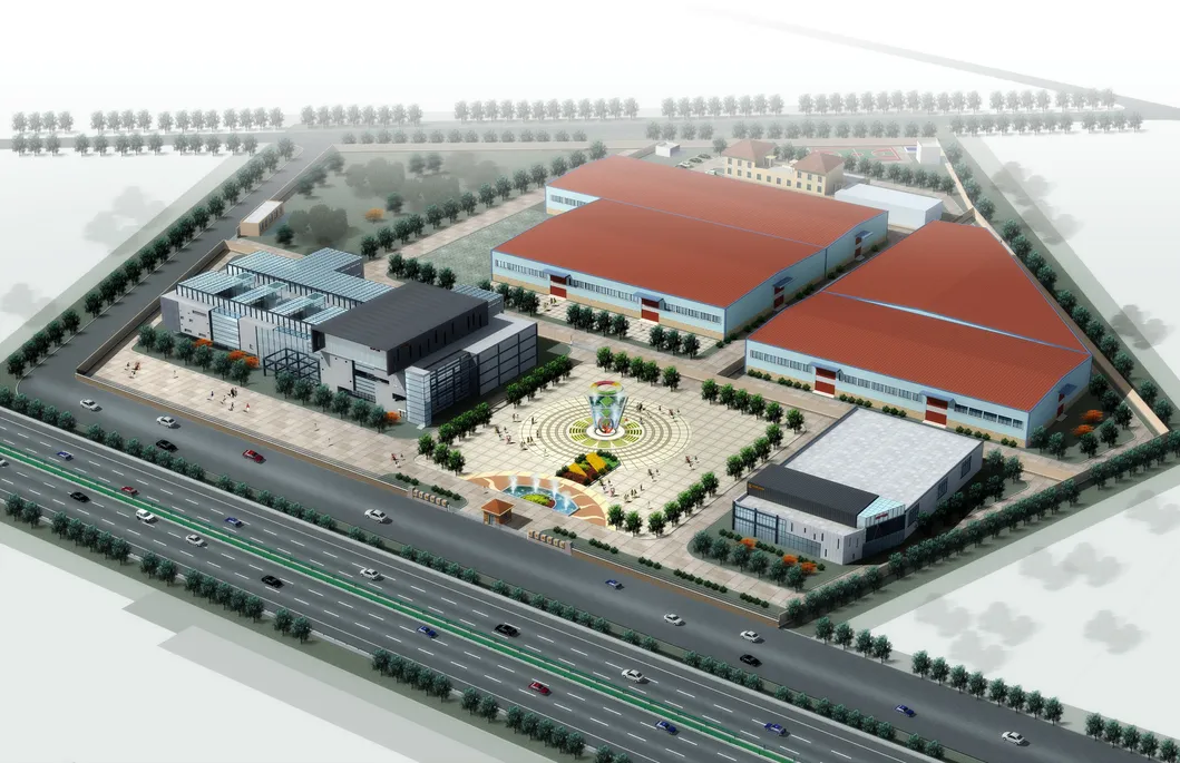
Price per square meter can be 25%-30% lower than conventional steel buildings. Site erection cost is low because of faster erection times and easier process.
All steel components are fabricated at the factory and linked by bolts at the site. Erection process is fast, easy to install. Requires up to 60% less construction time compared to R.C.C.
Flexible in any design requirement, easy to expand in the future and highly economical with low transportation costs.
Green solution for the environment with CO2 reduction, excellent energy efficiency, and full recyclability.
Pre-engineered metal buildings consist of the following components:
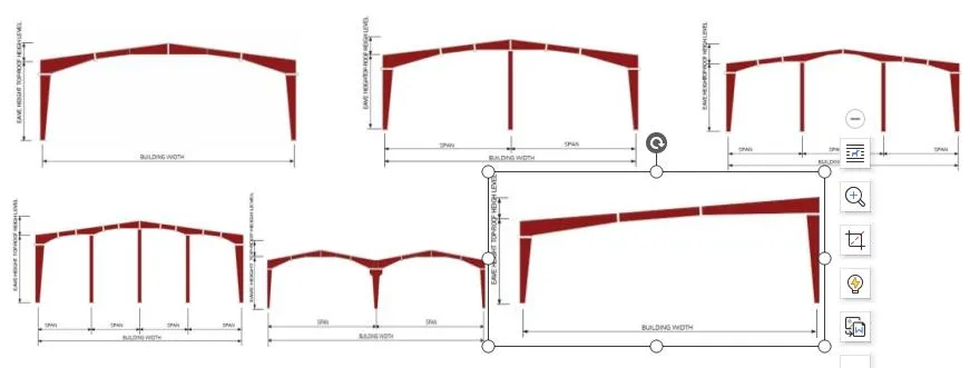
This statement describes the guidelines and methodology followed during fabrication, blasting, painting, and supply of pre-engineered structures.
Verification of receiving documents and quantity. Visual inspection by QC to confirm surface conditions, dimensional inspection (length, width, thickness), and verification of Mill Test Certificates (MTC) for traceability.
Preparation of Plates: Drawings are copied into plate processing machines. Automated drilling and plasma cutting are done based on expert NC software files.
Preparation of Beams/Tubes: Automated cutting and drilling machines process structural profiles before transferring them to the fit-up section.
Fabricators collect beams and plates to fix details like end plates, stiffeners, and purlin cleats by tack welding as specified in drawings before QC inspection.
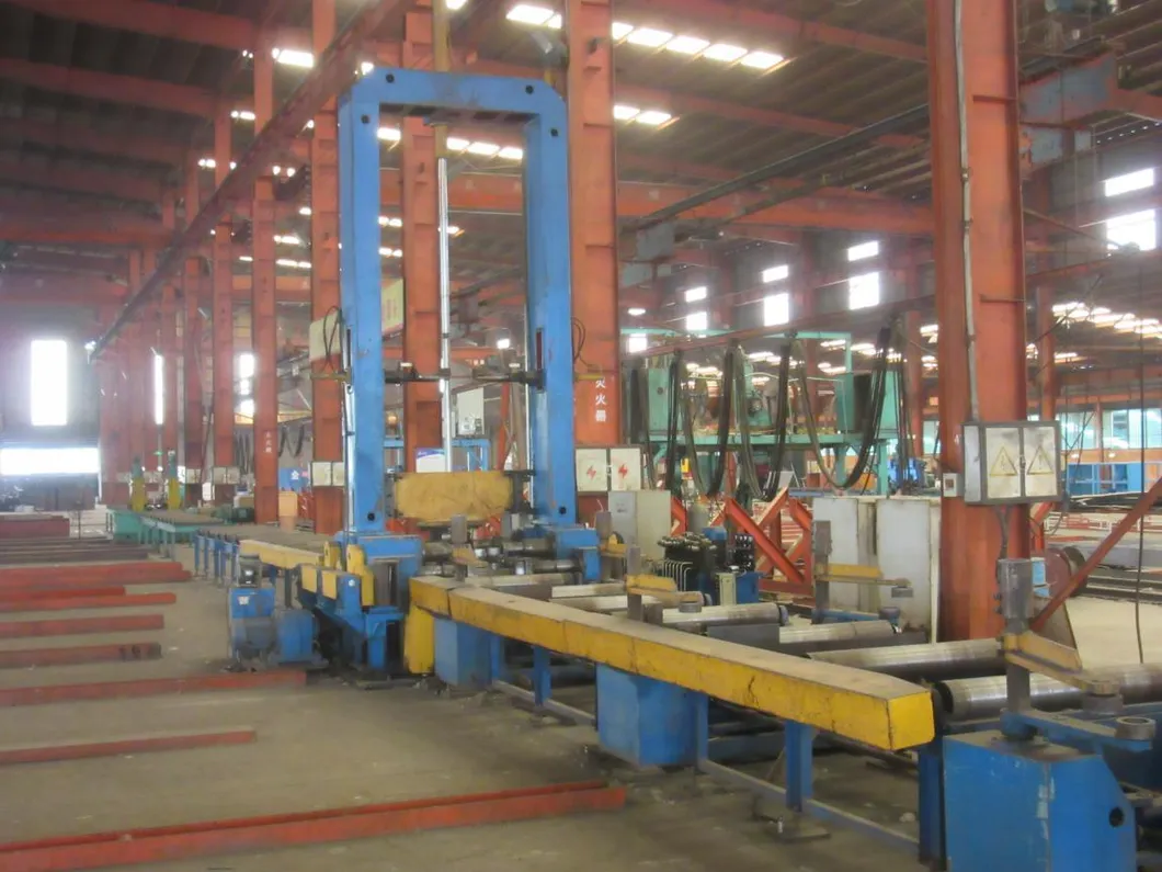
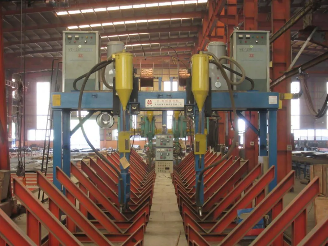
Performed using Submerged Arc Welding (SAW) and MIG Welding. Weld locations are cleaned of dust, oil, and grease. Fillet size parameters conform strictly to GB50661-2011 standards. Spatters, slag, and burrs are ground off clean.
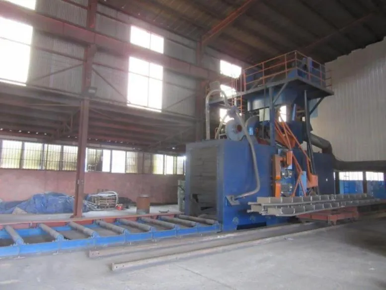
Automated blasting using 6 rotating high-speed wheels to clean substrates up to SA 2/2.5 grade. This ensures total removal of mill scale and rust prior to paint application.
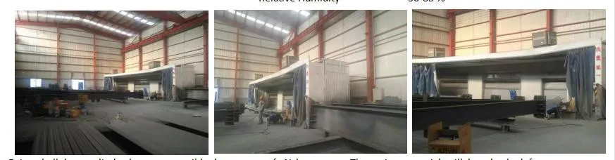
Performed under strictly checked environmental conditions (GB50205-2001). Paint is applied using Airless Sprayers. Target Dry Film Thickness (DFT) is verified by QC inspectors.
Finished components are stored logically in the yard job-wise. Dispatched via contracted transport companies as soon as loading clearances are issued.
Manufacturing process follows rigorous international and national standards (ISO9001 and CE). Key references followed:
Regulations established to improve standardization and ensure welded member structural reliability. Definition of fillet weld leg size (K) is monitored precisely.
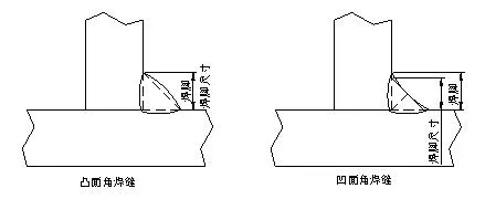
| Form of Fillet Weld Leg | K (Fillet Weld Size) Value | Note |
|---|---|---|
| Fillet weld without groove | K=(0.7~1)t and ≤15mm | For most of the steel structure buildings |
| Fillet weld without groove | K=(0.5~0.6)t | For strengthening ribs and other secondary members |
| Fillet weld with groove (CJP and PJP) | K=t/4 and K≤10mm | For most of the steel structure buildings |
| Fillet weld with groove (CJP and PJP) | K=t/2 and K≤10mm | Important members (crane beams or connections between web and flange plates) |
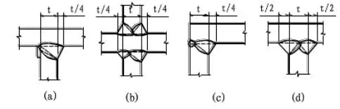
Processing uses high-purity gases (98% acrylic gas / 99.99% liquid oxygen) to guarantee flat cut surfaces. Strengthening of flanges uses heavy-duty straightening equipment to correct any thermal distortion from welding.

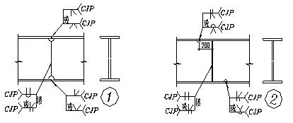
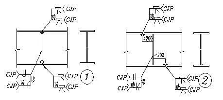
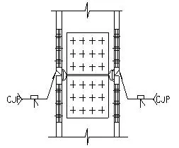
Choosing the correct groove form is vital for minimize filler metal volume, ease of operation, and reduction of structural stress distortion.
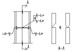
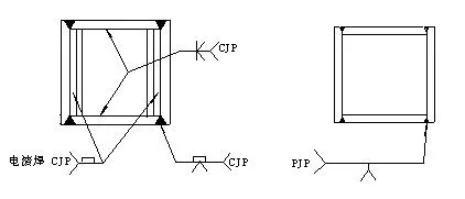
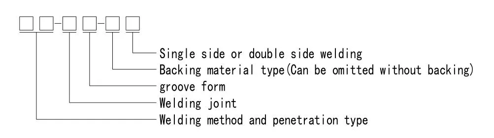
| Mark | Welding Method | Penetration Type |
|---|---|---|
| MC | Shielded metal arc welding | CJP - Complete Joint Penetration |
| MP | PJP - Partial Joint Penetration | |
| GC | Shielded arc welding / Self-shielded arc welding | CJP - Complete Joint Penetration |
| GP | PJP - Partial Joint Penetration | |
| SC | Submerged arc welding | CJP - Complete Joint Penetration |
| SP | PJP - Partial Joint Penetration |